Unity3D Surface Shader Tutorial
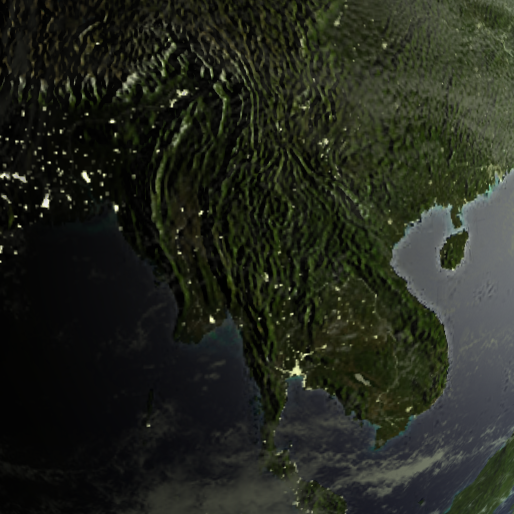
I’ve been meaning to learn about Unity’s Surface Shader paradigm since I saw Shawn White’s talk at Unite 2010 (newer 2011 version here). Shawn was our shader and visuals programmer during the Blurst period at Flashbang, so I rarely messed with shaders, but he became something of an expert. I finally got around to trying this out 2 years later and figured I would share the knowledge I gained. Here’s the final version of what I made, a model of Earth using NASA’s Blue Marble Next Generation dataset. Textures are big so it takes a bit to load. Click and move the mouse to rotate the camera. Take a moment to watch how lighting interacts with water (especially rivers), the transition from night lights to daylight along the terminator, and the way that clouds scatter light around the edge. I’ll explain how each of these effects is achieved below. The full shader files are here:
Blue Marble Surface Shader Demo
Normally shaders are written as two related programs in a single file – a vertex program that modifies vertex data (like position, normals, etc.), followed by a fragment or pixel program that takes interpolated vertex data for a single pixel and converts it into the final output color. This pixel program includes everything that normally makes a shader pretty – texture combines, lighting, etc. It’s also usually a horrible mess of maths, which can be daunting if you don’t have a degree in linear algebra. Speaking of which, here’s a tip when thinking about shaders, which use lots of dot products – the dot product is basically just the angle between two vectors, when both of those vectors have length 1. Specifically, a•b = cos(theta). So a•b = 1 => theta = 0 degrees, a•b = 0 => theta = 90 degrees, a•b = -1 => theta = 180 degrees.
The surface shader paradigm abstracts the pixel program into two steps – a surface program, that modifies the per-pixel properties of the surface (color, alpha value, surface normal, emissive light color, etc.) and a lighting program, that applies the lights to each pixel. This abstraction means that whenever you calculate a surface property, you should think about whether it is dependent on lighting. If yes, the calculation should go in the lighting program. If no, it can go into the surface program.
Picking Inspirations
A good way to learn shader programming is to try and emulate an effect you’ve seen somewhere else. I was interested in making a set of shaders that produced realistic looking planets, but I also specifically liked rim-lighting effects, and specular reflections on rivers.
Property and Program Declarations
Unity shaders start out with property declarations. These are the properties that will be exposed to the Material inspector and can be modified on a per-material basis. Here are the property declarations for the planet shader:
1
2
3
4
5
6
7
8
9
10
11
12
13
14
15
16
17
18
19
20
Shader "Custom/Earth" {
    Properties {
        _MainTex ("Diffuse(RGB) Spec(A)", 2D) = "white" {}
        _BumpMap ("Bumpmap", 2D) = "bump" {}
        _EmissionMap("Night Lights Map", 2D) = "white" {}
        _EmissionStr("Night Lights Strength", Range(0,1)) = 0.5
        _EmissionColor("Night Lights Color", Color) = (1.0, 1.0, 1.0, 1.0)
        _SpecColor ("Specular Color", Color) = (0.5,0.5,0.5,1)
        _Shininess ("Shininess", Range (0.01, 1)) = 0.078125
        _SpecPower ("Specular Power", Float) = 48.0
    }
    SubShader {
        Tags { "RenderType" = "Opaque" }
        CGPROGRAM
        #pragma surface surf PlanetSpecular noambient
        ...
        ENDCG
    }
    Fallback "Diffuse"
}
Each property has a name (which is the variable name in the Cg code, as well as the material property name in Unity), a description, a type (2D for textures, Range for sliders, Float for type-in values, etc.), and a default value. The first three in the example above are textures supplied to the shader, the others are colors or floating point values that give us knobs to turn to change the shader look. Here’s what the inspector for this shader ends up as:
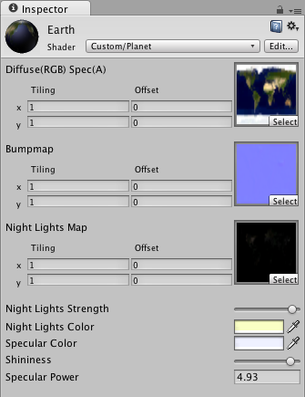
The actual Cg shader code goes within the Subshader{} block, between CGPROGRAM and ENDCG. The separate Pass{} blocks, which are normally used when writing fragment shaders, are generated automatically by the shader compiler – that’s the beauty of this higher abstraction level. The #pragma surface ... line tells the compiler that we’re writing a surface shader, and then tells it the names of our surface function (surf) and lighting model (PlanetSpecular). There are two built-in lighting models, Lambert (Diffuse) and BlinnPhong (Specular). If we give any other value, the surface shader will expect us to write that lighting function as well. The noambient part at the end is an optional parameter that instructs it not to apply scene-based ambient lighting. There are several other optional parameters, which are in the Surface Shader documentation. The Fallback "Diffuse" at the end of the shader tells it which shader to use if the current platform doesn’t support the shader we write. In fact simple Diffuse would not be a good fallback for this shader, so I should later change it to one that includes specular highlighting.
Surface Program
1
2
3
4
5
6
7
8
9
10
11
12
13
14
15
struct Input {
    float2 uv_MainTex;
    float2 uv_BumpMap;
    float2 uv_EmissionMap;
};
sampler2D _MainTex;
sampler2D _BumpMap;
sampler2D _EmissionMap;

void surf (Input IN, inout SurfaceOutput o) {
    o.Albedo = tex2D (_MainTex, IN.uv_MainTex).rgb;
    o.Specular = tex2D (_MainTex, IN.uv_MainTex).a;
    o.Normal = UnpackNormal (tex2D (_BumpMap, IN.uv_BumpMap));
    o.Alpha = length(tex2D (_EmissionMap, IN.uv_EmissionMap).rgb);
}
This is the surface program, which comes after the #pragma surface ... line above. It has three parts – definition of the input structure (i.e. what data we want per-pixel), variable declarations of the material-wide (non per-pixel) properties we want to use, and the surface function (surf), which we named in the #pragma surface ... line.
The input structure is any set of values that we want on a per-pixel basis. Usually this should include the uv coordinates of your input textures, named uv (or uv2 for the second coordinate set) followed by the texture name from the property definitions. The input structure can also contain some built-in values such as viewDir (the direction to the camera). The full list is again on the Surface Shader documentation page.
Next come variable declarations for per-material data. This includes the texture samplers for texture properties (remember, the shader loads the texture only once, and then samples it using the uv coordinates per-pixel), which are named the same as the properties. It also includes any per-material constants that will be applied before lighting, such as thresholding values.
The surface function is where the actual per-pixel, pre-lighting surface property calculations are done, and stored in the output structure. The output structure is the data that will be passed to the lighting model. The default structure is:
1
2
3
4
5
6
7
8
struct SurfaceOutput {
    half3 Albedo;
    half3 Normal;
    half3 Emission;
    half Specular;
    half Gloss;
    half Alpha;
};
While each of these have a specific meaning if you use the standard lighting models, you can think of them as simply three 3-vectors and three numbers where data can be stored. Some of them have specific semantic meanings in certain cases – for instance, Emission always appears to be combined with other lights before being passed to the lighting model (you can still access its value in your custom lighting function, but its value will also be added to other lights in the scene). Likewise Alpha has a specific meaning for alpha-blended shaders (like the Clouds shader below).
In the surface function for the Earth shader, I simply store the surface color in the Albedo variable, the surface specular reflectance (alpha channel of _MainTex) in the Specular variable, the surface normal vector in the Normal variable, and the emissive light (city night lights) in the Alpha variable. Two things to note here:
1) I stored the surface emissive light in Alpha instead of Emission because I can then control the strength of the surface lights based on other scene lights – i.e. I can turn off night lights when a pixel is illuminated by the Sun. If I had stored the emissive light in Emission, it would have been combined with the scene lights before being passed to the lighting model, and I would not have been able to control the two independently.
2) Right now, the shader uses three texture samplers – _MainTex for albedo and specularity, _BumpMap for surface normals, and _EmissionMap for the city lights. This is wasteful, since I only use the grayscale value of _EmissionMap. Instead, it might be smarter to pack the city lights into the alpha channel of _BumpMap. This would reduce to only two texture samplers, using both rgb and a values of each.
Lighting Program
1
2
3
4
5
6
7
8
9
10
11
12
13
14
15
16
17
float _Shininess;
float _SpecPower;
float _EmissionStr;
half4 _EmissionColor;

half4 LightingPlanetSpecular (SurfaceOutput s, half3 lightDir, half3 viewDir, half atten) {
    half diffuse = max (0, dot (s.Normal, lightDir));
    half3 lightView = normalize (lightDir + viewDir);
    float specStr = max (0, dot(s.Normal, lightView));
    float spec = pow (specStr, _SpecPower);
    half4 c;
    c.rgb = _LightColor0.rgb * atten * (s.Albedo * diffuse +
        spec * s.Specular * _Shininess * _SpecColor) +
        (saturate(1.0-2*diffuse) * s.Alpha * _EmissionStr * _EmissionColor);
    c.a = s.Specular;
    return c;
}
For this shader, this is where the magic happens. The first thing I do is declare the material property variables. In this case it’s three floats – two that control the specular reflection (_Shininess and _SpecPower) and one that controls the intensity of the night lights (_EmissionStr).
The lighting function is named based on the lighting model name you supply in the #pragma surface ... line. The default lighting function is simply Lighting<ModelName>, so in this case LightingPlanetSpecular. There are variants of this function signature based on whether or not the lighting model is view direction dependent (specular reflection is), as well as whether or not the shader works with deferred lighting, or needs to handle directional lightmaps. These are detailed on the Surface Shader Lighting Models page.
The per-pixel inputs to the lighting model function are the surface property structure from the surface program (SurfaceOutput s), the vector direction to the light (half3 lightDir), the vector view direction (half3 viewDir), and the lighting attenuation factor (half atten). The output of the lighting model is a half4 vector – the final RGBA color of the rendered pixel.
In the PlanetSpecular lighting model above, line 7 calculates the diffuse emission factor per-pixel, which ranges from 0 to 1. Lines 8-10 calculate the specular emission factor per-pixel, using the Blinn-Phong algorithm, which again ranges from 0 to 1.
Line 12 is where I set the final output color for the pixel. It is composed of the diffuse color term (_LightColor0 * 2 * atten * diffuse * s.Albedo), the specular color term (_LightColor0 * 2 * atten * spec * _Shininess * _SpecColor), and an emissive color term (saturate(1 - 2 * diffuse) * s.Alpha * _EmissionStr * _EmissionColor) for the night lights. Again, the diffuse and specular terms are totally standard Blinn-Phong. That’s it!
Night Lights
For the night lights, saturate(1 - 2 * diffuse) serves as the strength of the lights for the pixel, where saturate() is a Cg function that clamps a value between 0 and 1. It’s necessary so that you don’t get negative emissive lighting (black cities) when the diffuse term is 0.5-1. I used 1 - 2 * diffuse because I wanted the lights to turn on gradually as a city neared the terminator between daylight and night. Using only 1 - diffuse meant that lights would begin to turn on as soon as a city passed local noon, which looked unnatural (actually the 2 should probably be a tunable material property). By the time a city reaches the terminator, the diffuse term is 0 and the lights are fully on.
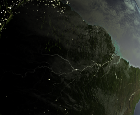
Emphasizing River Specular Reflection
I loved the look of the Amazon in the Flight404 example above, so I played around with the specular map (stored in the alpha channel of _MainTex), until I got an effect I liked. I eventually settled on selecting water using a false color map, the same one used for the Flight404 example. I used Photoshop’s Select Color Range tool to pick the water color, with the fuzziness cranked all the way up. I then ran an edge detection filter to emphasize the rivers. This also had the side effect of emphasizing shorelines, a subtle but really cool effect. I picked a silver-blue color for _SpecColor that contrasts well with the dark.
Cloud Shader
I wanted the cloud shader to approximate subsurface scattering in the atmosphere, like in the rim lighting planet shader in the inspirations section above. I didn’t like two things about basic rim lighting though – it is applied equally around the entire rim, and for shaders with bump maps (like the example one I linked), it looks ugly as all hell. So in the spirit of learning, I decided to write a custom shader for this, too. Here it is:
1
2
3
4
5
6
7
8
9
10
11
12
13
14
15
16
17
18
19
20
21
22
23
24
25
26
27
28
29
30
31
32
33
34
35
36
37
38
39
Shader "Custom/Clouds" {
    Properties {
        _MainTex ("Alpha (A)", 2D) = "white" {}
        _RimColor ("Rim Color", Color) = (0.26,0.19,0.16,0.0)
        _RimPower ("Rim Power", Float) = 3.0
    }
    SubShader {
        Tags { "RenderType"="Transparent" }

        CGPROGRAM
        #pragma surface surf WrapLambert alpha

        struct Input {
            float2 uv_MainTex;
            float3 viewDir;
        };
        sampler2D _MainTex;
        float _RimPower;

        void surf (Input IN, inout SurfaceOutput o) {
            half rim = 1.0 - saturate(dot (normalize(IN.viewDir), o.Normal));
            o.Specular = pow (rim, _RimPower);
            o.Alpha = tex2D (_MainTex, IN.uv_MainTex).a + o.Specular;
        }
        half4 _RimColor;

        half4 LightingWrapLambert (SurfaceOutput s, half3 lightDir, half atten) {
            half NdotL = dot (s.Normal, lightDir);
            half diffuse = max(0, NdotL* 0.9 + 0.1);
            half4 c;
            c.rgb = (atten * 2) * _LightColor0.rgb * diffuse * (1.0 - s.Specular)
                + (diffuse * s.Specular * _RimColor);
            c.a = s.Alpha;
            return c;
        }
        ENDCG
    }
    FallBack "Diffuse"
}
And here is the inspector:
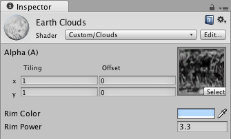
There are a few specific interesting things about this shader.
First, it’s an alpha blended shader (#pragma surface ... alpha). In surface shader parlance, this means that all we have to do is fill o.Alpha with the proper alpha value for the pixel and Unity will handle the actual blending. Cool, but it does mean we have to be careful about what we put in that variable.
Second, the rim-lighting calculation. Lines 21-22 are the standard way to do this – it’s based on the view direction (always around the edges from where we look), and increases in power as the surface normal points sideways from us, hence the 1.0 - dot(IN.viewDir, o.Normal). I store the value in o.Specular because I want to use lighting to later modify its visibility, so there isn’t rim light around the entire planet.
Third, the alpha value. I get the alpha value from the supplied _MainTex, but then I add o.Specular, because I want to make the rim lighting visible even if there aren’t clouds in a pixel (i.e. the alpha from _MainTex is 0).
Fourth, the lighting model is not a standard Lambert (diffuse) model, but is based on Wrapped Lambert, a modified diffuse shader where light is allowed to wrap around the edges of a surface. This again helps to fake subsurface scattering, because it lets the sunlight from the scene wrap slightly around Earth’s limb. Line 29 is where this happens, and we basically just take 90% of the normal diffuse factor, then add 10%. When we actually apply the lighting, we have a diffuse term (2 * atten * _LightColor0.rgb * diffuse * (1.0 - s.Specular)) and the emissive term (diffuse * s.Specular * _RimColor). By multiplying the rim factor (s.Specular) by the diffuse factor, I ensure that we only apply rim lighting where there is normally light. We just add some sky blue for scattered light if we happen to be looking through the atmosphere sideways. The diffuse term gets multiplied by 1.0 - s.Specular so that rim lighting always takes precedence, otherwise we would just get white light when a brightly lighted limb had the rim lighting added.

The end result of the rim lighting is decent, but I don’t like the hard edge between the limb and black space. This could be fixed by using a ramp texture for the rim lighting, where it slowly increases in intensity from center to limb, then falls off abruptly to simulate thinning atmosphere. That will be a test for another day though!
Update! Using a Ramp Texture For Rim Lighting
As I mentioned above I wasn’t totally pleased with how the rim lighting looked. Since its strength was 100% at the edge, it looked too stark against the black of space. Earth’s real atmosphere is very thin and quickly fades to nothingness if you look at the horizon from space. So instead of the mathematical power-law that I was using, I replaced the clouds surface function with one that uses a “ramp texture” to map viewDir•normal to actual opacity. This lets the artist (me!) pick any gradient that looks good, rather than just changing the power law index.
1
2
3
4
5
6
7
8
9
10
11
12
13
14
15
16
17
18
19
20
...
Properties {
	_MainTex ("Alpha (A)", 2D) = "white" {}
	_AtmosRamp ("Atmosphere Ramp (RG or B)", 2D) = "black" {}
	_RimColor ("Rim Color", Color) = (0.26,0.19,0.16,0.0)
}
...
struct Input {
	float2 uv_MainTex;
	float3 viewDir;
};
sampler2D _MainTex;
sampler2D _AtmosRamp;

void surf (Input IN, inout SurfaceOutput o) {
	float2 uv_Ramp = 1.0 - saturate(dot (normalize(IN.viewDir), o.Normal));
	o.Specular = tex2D (_AtmosRamp, uv_Ramp).r;
	o.Alpha = tex2D (_MainTex, IN.uv_MainTex).a + o.Specular;
}
...
Line 16 generates the UV coordinate where we sample the ramp texture (this syntax makes both u and v coordinates the same, but the texture is the same on every line in the y direction). Here’s the inspector:
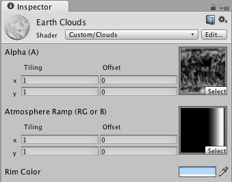
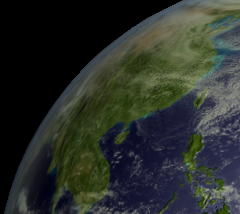
This looks much, much nicer, and can be tuned easily by simply using a different gradient in the texture. I also gave the sphere model an upgrade with more triangles, so it doesn’t look so ugly on the edge! Here’s a comparison to the above picture that used just power-law rim lighting:
Useful Surface Shader Learning Links
- Unity Manual: Writing Surface Shaders – Includes all the #pragma surface optional flags
- Unity Manual: Surface Shader Lighting – Very brief, but gives naming conventions for lighting functions
- Unity Manual: Surface Shader Examples – Some good examples but on a rather boring model
- Unity Manual: Surface Shader Lighting Examples – Good examples for lighting models (toon ramp for instance)
- Unity Manual: ShaderLab Bultin Values – some predefined variables you can use in Cg programs
- Cg Tutorial: Standard Library Functions – Cg functions you can use in your shaders. Note that noise() doesn’t work in Unity?
- Cg Tutorial: Lighting and Lighting Models – For more information on lighting models
- Flight 404 – Rad visualization porn for inspiration